- Introduction and overall specs
- Pouch and prismatic
- EV conversion configurations
- Battery management system
- Using original Volkswagen hardware
- Connecting an aftermarket BMS
- Validating cell tap connections!
- Dummy MEB module
- n-BMS cell tap validator
- Cooling / heating modules
- Charging
Introduction and overall specs
With their MEB platform, Volkswagen has set a new standard for their battery system. Main requirements when developing this system was scalability, usable for both 2wd and 4wd, lightweight, easy to assemble, integrated cooling and adaptable to different cell types. As a result these Volkswagen MEB battery modules are also very interesting to use in DIY EV conversions.
The battery box has integrated cooling/heating in a double floor and is completely isolated from the battery modules. Currently there are three battery packs made out of two module configurations: 12s2p (VW part 0Z1915592H) and 8s3p (VW part 0Z1915599H) both with a gross capacity of 6,85 kWh. The module is standardized in terms of form factor and has 24 cells inside. The weight of one MEB module is 32 kg.
Volkswagen builds the following packs with these modules
- 7x 12s2p = 48 kWh (usable 45 kWh in ID.3 Pure, WLTP 330 km)
- 8x 12s2p = 55 kWh (usable 52 kWh in ID.3 Pure Performance, WLTP 348 km)
- 9x 12s2p = 62 kWh (usable 58 kWh in ID.3 Pro, WLTP 420 km), VW part 0Z1915911N
- 12x 8s3p = 82 kWh (usable 77 kWh in ID.4, ID.5 and ID.Buzz), VW part 0Z1915910N
The modules are also used/found in the Cupra and Skoda.
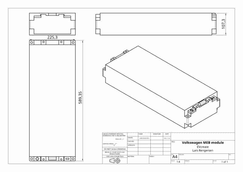
There are multiple manufacturers that make these modules for Volkswagen. Currently we see modules made by LG (full metal laser welded case) and by CATL (plastic removable cover).
Pouch and prismatic
The modules made by LG contain pouches and modules made by CATL have prismatic cells.
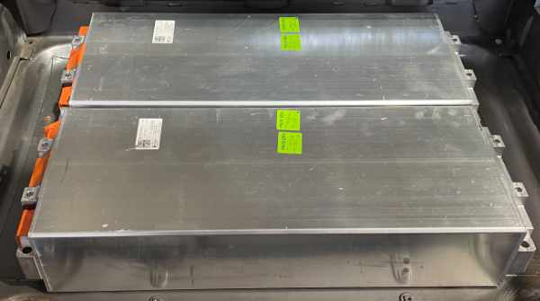
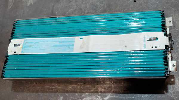
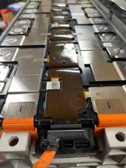
Unfortunately I have not been able to find any official datasheets on these cells. What I’ve been told is that the prismatic cells tend to be a bit more capable in terms of current they can deliver.
The ID.4 GTX is a dual motor edition with 220 kW power so the 8s3p is at least capable of that. Depending on the thermal management and duration probably higher outputs are possible. I’ve read that the 2p modules are good for 800A up to 10 seconds so that means the 3p’s could do 1200A.
EV conversion configurations
Most high voltage conversions are 96S so that means the following configurations are common:
| Modules | Config | Gross | Usable | Weight | Pack |
|---|---|---|---|---|---|
| 8x | 12s2p | 55 kWh | 51 kWh | 256 kg | 96s2p |
| 12x | 8s3p | 82 kWh | 77 kWh | 384 kg | 96s3p |
Using nine 12s2p modules like Volkswagen does might be a challenge in terms of max. voltage ratings of components used. At 108s when charging up to 4,15V per cell the pack voltage will rise to 448V. For example for the Nissan Leaf inverter this is too high.
Battery management system
The modules have an external cell monitoring unit. So the module control connector provides access to the cell taps and two thermistors. Pinout details will be provided below. Selecting a BMS to use with the MEB modules is not trivial since the balancing current of the Volkswagen BMS is very low. They only use around 100 mA of passive cell balancing. Higher currents could damage the cell tap wires in the modules. On Openinverter it was reported that some modules have a 750 mA SMD fuse.
G-code (=750 mA) fuses confirmed in a LG 8s3p module.

100 mA max. cell balancing current
Below you will find the cell balancing current details of some aftermarket battery management systems:
| BMS | Balancing current | Comment |
|---|---|---|
| Orion 2 | 200 mA | Fixed |
| Lithium Balance s-BMS | 840 mA | Fixed |
| Lithium Balance n-BMS | 200 mA | Can be lowered via PWM control |
| Emus | 420 mA | Can be lowered in steps of 10% |
Since the balancing current is not a continuous current the load the cell taps can handle might be more than the 100 mA Volkswagen uses. So I decided to do a test. I used Lithium Balance s-BMS and installed a CAB500 current sensor.
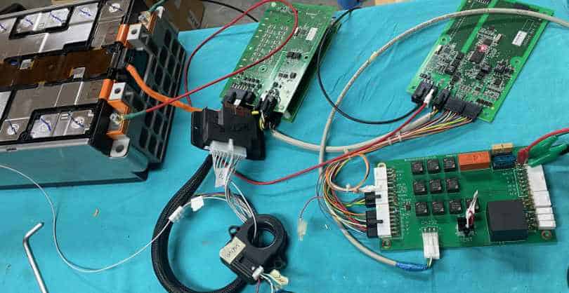

From the above you can see the balancing current was 647 mA at a cell voltage of 3,9V. In the end I charged up to 4,1V per cell and saw a balancing current of 682 mA and the cell tap ribbon cable did not burn.
Additionally I did a test where I applied a load of 840 mA to a CATL module cell tap. Did not blow within two minutes.
Furthermore I tested a G-code SMD fuse (466 series) and that blew instantly at 1,25A.
These tests were performed at room temperature and for only a short duration. At higher temperatures, fuses blow faster. So I’d still recommend to use a BMS that allows you to set the maximum balancing current to 100 mA.
For me that rules out using Lithium Balance s-BMS but since it’s cell monitoring units support up to 8s it is not usable for the 12s modules anyway. Myself I’ll be using Lithium Balance n-BMS with these modules.
Using original Volkswagen hardware
Safest way forward to ensure the modules are treated within their original design intent is to re-use the original cell monitoring system from Volkswagen. These communicate via 500 kpbs CAN-BUS with the master. You can build your own integration (see Tom-evnut’s Github : VW-bms for further info) or use SIMP that builds on this info (developed by Tom de Bree and currently available from Citini as EVS) or use GrnBMS (developed by Pro-LOX). The downside is that these solutions do not come with CE, E-mark and ECE certifications. So depending on your own requirements and/or those from inspecting authorities these might not be usable in EV conversions.
But if not having these certifications are no issue it is an interesting option. The GRNbms kit is available via EVcreate.
GRNbms
-
 GRNbms battery management system kit€985,00 (inc. VAT €1.191,85)
Supported CMUs
- Volkswagen MEB 12S CMU full control and balancing, from 1-32 modules
- Volkswagen MEB 8S CMU full control and balancing, from 4-36 modules
- BMW i3 CMU full control and balancing (Beta) 1-32 modules
- BMW i8 CMU full control and balancing (Beta) 1-36 modules
Supported Inverters
- Victron canbus communication to Victron GX devices
- Sofar HYD high voltage inverter communication (Beta)
- Sofar HYD low voltage inverter communication (Beta)
- Goodwe ES/BT KTL series inverter communication (Beta)
Connecting an aftermarket BMS
As mentioned above, you can connect an aftermarket BMS to the Volkswagen MEB modules. In case you buy separate modules, getting the cell tap cables might be a challenge and the connectors are restricted so cannot be ordered directly at TE.
Both the cell tap cable for the 8s module (white cover at the module end) and for the 12s module (black cover at the module end) is available from EVcreate.
When connecting the module to an aftermarket BMS using an original cell tap harness, we will remove the blue or brown connector. Never do this with the cable plugged into a module!
MEB 12s module pinout
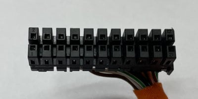
Row 1: Even numbers 2 to 22
Row 2: Odd numbers 1 to 21
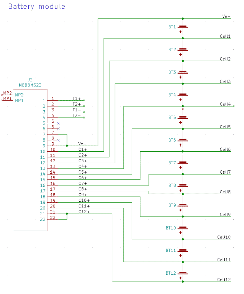
So this is visualized as per the below schematic.
- Thermistor 1 +
- Thermistor 2 +
- Thermistor 1 –
- Thermistor 2 –
- Not connected
- Not connected
- Module – (Ve-), CMU power negative
- Not connected
- Ve- / Module negative / first cell negative
- Cell 1 positive
- Cell 2 positive
- Cell 3 positive
- Cell 4 positive
- Cell 5 positive
- Cell 6 positive
- Cell 7 positive
- Cell 8 positive
- Cell 9 positive
- Cell 10 positive
- Cell 11 positive
- Cell 12 positive
- Module + (Cell 12 positive), CMU power positive
Cell tap wiring harness
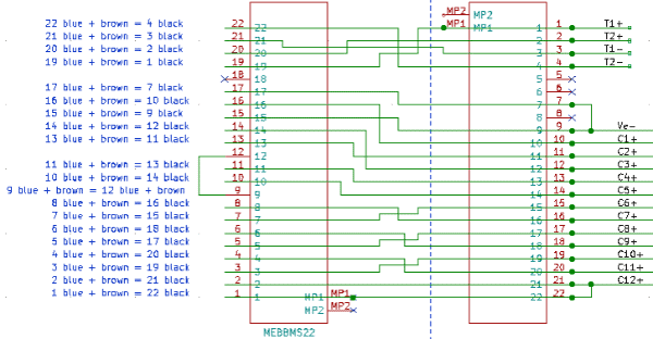
The pinout of the black cover connector is not one to one mapped to the blue and brown connectors. That mapping is as per the below table and diagram.
- Module + (Cell 12 positive), CMU power positive
- Cell 12 positive
- Cell 10 positive
- Cell 11 positive
- Cell 8 positive
- Cell 9 positive
- Cell 6 positive
- Cell 7 positive
- Blue / brown 12
- Cell 5 positive
- Cell 4 positive
- Blue / brown 9
- Cell 2 positive
- Cell 3 positive
- Ve- / Module negative / first cell negative
- Cell 1 positive
- Module – (Ve-), CMU power negative
- Not connected
- Thermistor 1 +
- Thermistor 2 +
- Thermistor 1 –
- Thermistor 2 –
Blue and brown connector to black connector
Instead of re-using the original cable to make a new harness, I also developed helper boards. These breakout the celltaps and the termistors but not the VE- and Module + for powering a CMU.
-
 Volkswagen ID.3 / ID.4 (MEB) 12S battery module BMS cell tap board€49,00 (inc. VAT €59,29)
The board accepts the cell tap cable and the other end is an easy to obtain and crimp Molex connector (supplied with the board).
Unfortunately most of the time these boards are out of stock. Customers buying modules are prioritized. Sourcing the blue and brown connectors is a challenge as these are harvested from Volkswagen CMU’s due to the fact that this is a restricted TE item.
Especially nowadays where I need the same headers for the dummy / test 12s MEB modules.
MEB 8s module pinout
The 8s module uses the same inner connector as the 12s MEB module. Only difference is the cover and from that also the keying. The 8s MEB module has a white cover. To recap, the pin numbering of the connector is as per below:

Row 1: Even numbers 2 to 22
Row 2: Odd numbers 1 to 21
The assignment of pin 1 to 14 is identical to the 12s connector. However, pin 14, 15, 16 and 17 also output the voltage of cell 4. Pin 18 to 22 again have the highest cell taps. So this is visualized as per the below schematic.
- Thermistor 1 +
- Thermistor 2 +
- Thermistor 1 –
- Thermistor 2 –
- Not connected
- Not connected
- Module – (Ve-), CMU power negative
- Not connected
- Ve- / Module negative / first cell negative
- Cell 1 positive
- Cell 2 positive
- Cell 3 positive
- Cell 4 positive
- Cell 4 positive
- Cell 4 positive
- Cell 4 positive
- Cell 4 positive
- Cell 5 positive
- Cell 6 positive
- Cell 7 positive
- Cell 8 positive
- Module + (Cell 12 positive), CMU power positive

Cell tap wiring harness
As with the 12s connector, also the pinout of the white cover connector is not one to one mapped to the blue and brown connectors. The pinout of the blue/brown is similar though (with the difference being that only 8 cells are present). That mapping is as per the below table and diagram.
- Module + (Cell 8 positive), CMU power positive
- Cell 8 positive
- Cell 6 positive
- Cell 7 positive
- Cell 4 positive
- Cell 5 positive
- Cell 4 positive
- Cell 4 positive
- Blue / brown 12
- Cell 4 positive
- Cell 4 positive
- Blue / brown 9
- Cell 2 positive
- Cell 3 positive
- Ve- / Module negative / first cell negative
- Cell 1 positive
- Module – (Ve-), CMU power negative
- Not connected
- Thermistor 1 +
- Thermistor 2 +
- Thermistor 1 –
- Thermistor 2 –
Blue and brown connector to black connector

Validating cell tap connections!
Once you have prepared your harness it is important to validate the harness. Connecting a battery module can be tricky. If you made a fundamental mistake and introduced a short, your module might become useless. Therefore I developed 12S and 8S dummy modules and a cell tap validator for n-BMS.
The validator in the video is the tester by Batrium with an extension board to easily plug in the n-BMS CMU cell connector.
The PCB is a dummy test MEB module. The pinout is identical to a 12s or 8s MEB battery module. This allows you to test your wiring after modifying cables to protect your expensive battery module.
-
 Test 8s MEB battery module Volkswagen€65,00 (inc. VAT €78,65)
 -
 Test 12s MEB battery module Volkswagen€75,00 (inc. VAT €90,75)
More to come…
This blogpost is not finished yet and I’ll keep updating it and adding more info. But I thought the above was already worth sharing. To be added:
- Cooling / heating modules
- Charging
Feedback welcome
Any feedback, additions, suggestions for improvement is welcome. Please contact me by e-mail.
Share & link
Do you like this article? Please share and link (and not copy paste).

Hello,
I am intrested in your work. I own 2 of 0z1915592h batteries, which I will use as a battery pack for my solar system.
I found out BMS from DALY, which I am planning to use in my project.
It will be 12s 48V 120A bms. I am planning to use one for each module, it means 2 BMS for my 2 batteries. What do you think about these BMS’s?
I’ve seen Daly BMS but what I’ve not been able to find is a manufacturer website with product datasheets.
Is it any good? I don’t know.
Will it work with MEB? Perheps.
But since the MEB modules are designed for low balancing currents I’d only recommend a BMS that has a known and low max. balancing current.
For Daly I’ve not found any data.
That alone is already an indicator for me not to use it.
hell guys, I have 12S and 8S modules new, rejected. Just 1 cell is faulty in every pack and takes down 1 section. Is it easy way to remove cells from the metal case? I have them in EU. any interested for 429 EUR/6,85kWh?
These modules are rejected for a very good reason. In my view it is potentially dangerous to use them with such a high delta. This even sometimes happens to modules that come from cars that are on the road. Therefore I developed a Volkswagen MEB battery tester helper kit for iCharger X12 to make proper checking easier.
Think it is related to this recall Possible battery problem with 10,000 VW ID.3 and ID.4
So please do not tempt people with such low prices to use these and please have them recycled!!
Hello do you have any information on the thermistor that are inside the modules (law or table to convert the resitance into temperature) ? I am looking to reuse thoose temps in a bms.
Anyway thank you for this article !
Thanks! You are welcome.
I still need to write the section on cooling and heating and that’s where the thermistor info would be.
Not 100% confirmed yet, but I believe it is a 10K NTC with β 3380K.