The first version of a DIY DC CHAdeMO fast charging kit was developed in 2015 by Paulo Almeida, Damien Maguire, Collin Kidder and Jack Rickard. It used the JLD505 developed by Paulo Almeida and Celso Menaia. As per mid 2019, the latest version available was a CHAdeMO Interface v0.3 designed by Paulo and updated by Celso (New Electric) and further developed into v1 and v1.1 by New Electric.

Table of contents
- Open source (how it all got accelerated)
- CHAdeMO process (explaining how it works)
- Hardware version v2.0 (pinout and backwards compatibility)
- Wiring the CHAdeMO controller (how to install it in your car)
- CHAdeMO software (enhancements and configuration)
Open source
To accelerate the development and increase availability for the DIY community, New Electric shared the designs and latest version of the CHAdeMO fast charging software with Damien Maguire (www.evbwm.com). He implemented some changes and shared it as open source. Since that design only had single CAN-BUS it was limited in using data on voltage and current that was already available from a BMS or external sensors.
As a result Damien decided to change the approach for the CHAdeMO fast charging controller and started using the same hardware as his Leaf VCU V2. Later on he created a dedicated CHAdeMO board.
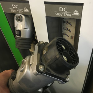
Bottomline is that a SAM3X chip (like the Arduino Due) was used instead of the Atmega328. That change was 90% a software change since the code had to be ported from the Atmega328 to the new SAM3X chip. The heavy lifting for this is taken care of by the compiler (Arduino IDE or Visual Studio Code + PlatformIO). Furthermore a CAN-BUS shunt had to be added as new current and voltage source and some legacy from the JLD505 had to be dropped. Isaac Kelly (www.electricboxster.com) took up this challenge and with the support of Damien he updated the software to a 0.6 version that worked together with the Leaf VCU V2 hardware (with some addons / modifications).
CHAdeMO process
As mentioned in “Introducing DC fast charging“, the communication for the CHAdeMO fast charging process is via CAN-BUS. The process is initiated by inserting the charge plug. The proximity pin triggers a wake-up of the controller. On it’s turn the controller provides an active low signal and 12V+ output (500 mA max) so you can use either one to wakeup other components such as the battery management system and put the car in charge mode.
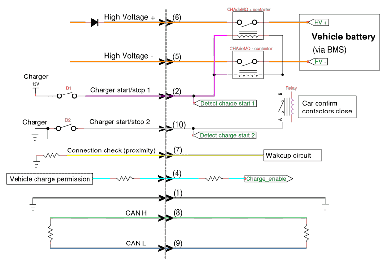
As soon as the plug is inserted and the user presses “Start” on the charger, the EVSE (charger) initiates the charge process. It is a combination of messages over CAN-BUS and analog signals. In the CHAdeMO fast charging approach the charger start/stop 1 is 12V ‘signal’ capable of delivering up to 2 A and is used to drive contactors. This approach gives the charger the opportunity to open contactors directly if needed. The whole sequence is explained below.
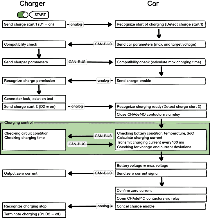
While the CHAdeMO protocol is accessible for members of the CHAdeMO Association only, there are many leads for achieving a DIY controller. For example, the digital communication (CAN messaging) is defined in the IEC 61851-24 standard (Electric vehicle conductive charging system – Part 24: Digital communication between a d.c. EV charging station and an electric vehicle for control of d.c. charging) which I purchased.
Hardware version v2.0
EVcreate developed the version v2.0 hardware as a drop-in replacement for the New Electric v1.1 by keeping the pinout the same and maintaining isolated CAN-BUS. It is NOT compatibele with earlier versions since those use a different pinout.
-
 CHAdeMO controller for DC fastcharge€495,00 (inc. VAT €598,95)
It currently is available for ‘early adopters’. Send me an e-mail for more info.
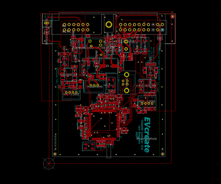
The controller has a Cinch enclosure and header with Molex MX150 connectors. To be exact, the ME-MX Header 5810132011 is used. This is a 32 I/O header with a 20 position A connector and a 12 position B connector.
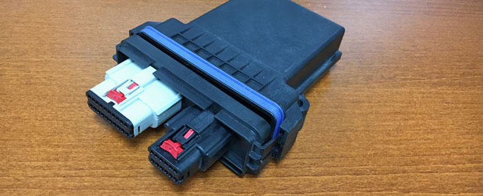
The A connector is for the integration in the car and the B connector is used to connect to the CHAdeMO fast charging outlet.
A) connector
A1 = Not connected
A2 = GND (for contactor feedback)
A3 = Not connected
A4 = USB D-
A5 = USB D+
A6 = CHAdeMO HV contactors coil GND
A7 = 12V output (500 mA max) when on
A8 = 12V in (always on)
A9 = CHAdeMO HV contactors coil +
A10 = Incoming Car CAN-H
A11 = Outgoing car CAN-H
A12 = Outgoing car CAN-L
A13 = Not connected
A14 = USB GND
A15 = USB 5V+
A16 = CHAdeMO HV- contactor feedback
A17 = Active low (GND) when on
A18 = CHAdeMO HV+ contactor feedback
A19 = GND
A20 = Incoming Car CAN-L
B) connector
B1 =GND
B2 = Charge start 1
B3 = Not connected
B4 = Charge enable
B5 = Not connected
B6 = Not connected
B7 = Proximity
B8 = CAN H
B9 = CAN L
B10 = Charge start 2
B11 = Not connected
B12 = Not connected
Enhancements in v2.0
New to the v2.0 hardware are the following features:
- Dual CAN-BUS (one dedicated for CHAdeMO and another one to communicate with the car
- Car CAN-BUS in and out for easy daisy chaining to other nodes
- Optional car CAN termination by soldering two pads
- CHAdeMO contactor feedback inputs
- Active low (GND) and 12V+ output (500 mA max) when on
- CAN bus now with common mode choke, ESD protection and split termination
- Increased robustness against 12V circuit over-voltage and 12V circuit over-current
- 12V+ and GND power connector on the PCB to easily power it for configuration on the bench
- USB connector on the PCB including wakeup on USB plug insertion
Things that were already good in V1.1 were kept, such as:
- Isolated inputs using optocouplers
- USB connections in connector A to easily program and monitor while installed in a car
- Isolated CAN-BUS
Wiring the CHAdeMO controller
To install the CHAdeMO fast charge controller in your car is quite straightforward. There are three main areas:
1. Yazaki socket to controller
The number on the Yazaki outlet matches one on one with the Cinch / Molex B-connector. So Yazaki 1 goes to B1, 2 to B2, etcetera. Only exceptions are pin 3 (which is not connected) and the high voltage connections 5 and 6 which do not go into the controller.
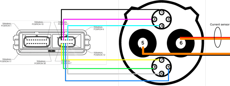
Connections presented looking from the front end into the connector / socket.
2. Current sensor
The CHAdeMO controller requires input on the charging current and voltage measured by the car. This is compared with the values measured / indicated by the charger. In case the deviation is too big, an error is triggered and the charing process stops.
The previous versions of the CHAdeMO fast charge controller up to v1.1 used a shunt and voltage divider to get information on voltage and current. However that required high voltage inputs into the controller. Getting this data over CAN-BUS increases the safety. Most robust and therefore supported way of implementing a current sensor is direct (as shown above) using a sensor on the CHAdeMO high voltage wiring (either + or -).
Using a direct current sensor is the most straightforward approach. By measuring the current directly on the CHAdeMO high voltage wiring the CHAdeMO fast charging controller and use this data directly.
Suggested and supported sensors are the LEM CAB300, LEM CAB500 or the IVT Current sensor.
-
 IVT current sensor€120,00 (inc. VAT €145,20)
 - Product on sale
 LEM CAB300 current sensor€130,00 (inc. VAT €157,30)
 -
 LEM CAB500 current sensor€150,00 – €260,00
3. Car integration
Basically what the controller needs is power, CAN-BUS, trigger the car charge mode and to control the HV contactors.
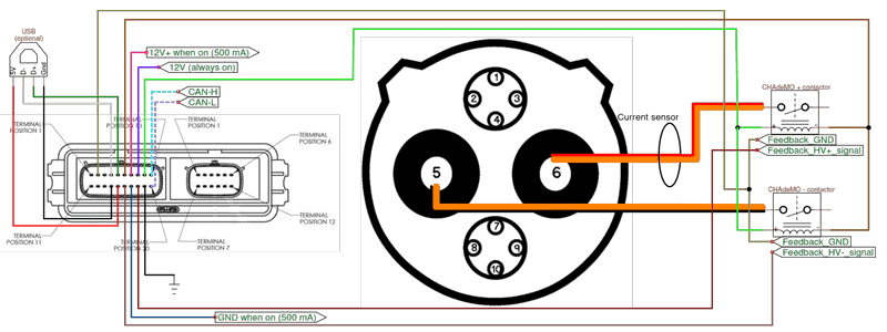
The USB connection is optional as well is the contactor feedback. The maximum allowed power draw of the two CHAdeMO contactors together is 2A.
CHAdeMO software
The CHAdeMO software was originally mainly developed by Collin Kidder (still doing awesome stuff, Collin80 on Github). It has been improved by New Electric based on field experience and fixes to address issues.
Currently EVcreate is working on further improving the software / CHAdeMO DIY library.
This paragraph will be updated as soon as more details are available.
Blog series on DC fast charging
- DC fast charging, an introduction
- CHAdeMO fast charging in DIY
- CCS fast charging in DIY
- Nissan Leaf CCS fast charging
- EVcreate CCS fast charging solution including AC onboard charger control
- High power = up to 500A peak (250A nominal)
- Low power = up to 125A max.
Feedback welcome
Any feedback, additions, suggestions for improvement is welcome. Please contact me by e-mail.
Share & link
Do you like this article? Please share and link (and not copy paste).

Lars,
Any chance of a diy CHADEMO 3 phase 32A 20-30 kWh charger kit…??
best Carel
Thanks for your interest. No, not likely on short term, Carel. I’m focussing on the vehicle side.
Regards,
Lars
Thank you for sharing this brilliant solution
My question is, once the CHADEMO relays are closed, can I draw power from the car instead of charging it? (I am considering V2L)
That will strongly depend on the controller that is managing the CHAdeMO charging process. The CHAdeMO controller I’m offering can detect a current deviation error. So in that case it strongly depends on where you draw that power. Furthermore it depends on how you achieve “once the CHADEMO relays are closed”. I’d say with the right approach it is possible but certainly not trivial.
What are the requirements for the HV contactors for the CHAdeMO?
Considering a pair of TE 2138011-1 for CHAdeMO, since I’m planning another pair for CCS. My battery pack is under 350VDC.
As stated above “In the CHAdeMO fast charging approach the charger start/stop 1 is 12V ‘signal’ capable of delivering up to 2 A and is used to drive contactors.” So you need to select contactors that together meet this max current. Furthermore you need contactors that do not depend on an external economiser since the charger start 1 (12V) and 2 (GND) do not ‘economize’ anything. The 2138011-1 therefore is not suitable as the coil would overheat and burn.

Source: TE 2138011-1 datahseet
Hi lars,
is there any issue about welding the contactor while close the contactor, I did not see any precharge or something else circuirt to limit the inrush?
At the beginning of the charge cycle the car will close the contactors of it’s high voltage circuit. As part of that procedure precharge will be done. Once that is ready and the ‘car is ready to receive charge’ it flags that to the controller and the controller and charger proceed with the charging. During the charging the CHAdeMO charger takes care of regulating the voltage (but that’s not really relevant since precharge has already taken place).
Hello and thank you for offering this board. In section “2. Current Sensor”, you mention that current and voltage measurements to the controller are needed so that they can be compared with the vehicle measurements, and charging will stop if the deviation is too large. Can this part of the process be bypassed somehow, such as by simply repeating back the vehicle’s current and voltage measurements? If not, then what can you recommend for a CAN voltage measuring sensor? Will the controller and vehicle automatically detect the sensors on the CAN BUS? I am thinking I would have to use a voltage divider for the voltage sensor to bring down the HV voltage. But then the CAN measurement would need to be calibrated to actual voltage, yes?
Also, I am wondering what the minimum charging power or current is allowable. I may want to charge with as low as 1 amp, and only up to 10 amps (into battery HV voltage).
The charge current may fluctuate, perhaps changing at a slew rate of 4 amps per second between 1 amp and 10 amps. How fast can the vehicle and controller track changes in charging current to prevent shut down of charging? Your thoughts?
Thanks again for the great work!
The process / the controller needs the car-side current and voltage via CAN. This can come from various sources. Voltage indeed most of the time comes from the battery management system, but can also be from a voltage + current shunt such as the IVT. Probably there are more ways to achieve voltage data in the correct structure via CAN, but using an IVT is the most straightforward one.
For measuring the charge current I recommend using a dedicated CAN current sensor such as the LEM CAB. This is due to the fact that if there are devices using current (eg DC/DC or airconditioning compressor) this current will not be measured by the BMS and can lead to false positive deviation errors.
I don’t have any data for that kind of low currents. At higher battery temperatures and higher state of charges by BMS lowered the ‘Maximum allowed DC charge current’ and this was processed in the CHAdeMO controller and send to the charging station via CAN.
In the controller you can set a low minimum charge current, but that’s only part of the story. And there is a maximum ramp up and down rate.
Furthermore I’m not sure if a charging station would allow / accept such low currents (for longer periods of time) or if it then would stop the session.
But what’s the point of implementing CHAdeMO?
10A at 355V = only 3,5 kW. Even a small OBC can almost do that.
The reason I want to explore using CHAdeMO instead of OBC is because OBC has a minimum charging power of 800 watts or so. I want to use a fluctuating off-grid power source that provides a range of 100 watts up to 3000 watts and I want to harvest the entire range. I want to actively control the charging power such that the impedance of the power source is always matched to the load, as the impedance at the power source will be fluctuating as well, so therefore the power may fluctuate a lot during charging. OBC does not have much range of power input so that is why I want to explore CHAdeMO since it offers a more direct connection to the EV battery.
Well, I guess it depends on the capabilities of the OBC and the charge controller.
I think the Thunderstruck TSM2500 could do it.
In their EVCC you can also set a very low charge end current (for the balancing phase).
Then you’d need to develop your own charge controller to control the TSM2500 and set the current aligned with the available power.
A CHAdeMO DC charger + CHAdeMO controller sounds overkill to me, but technically it should be possible but it strongly depends on what the CHAdeMO DC charger allows.